555 Timer Application
- 555 Timer Application Note
- Touch Sensor Using 555 Timer Applications
- 555 Timer Applications Pdf
- 555 Timer Application Circuits
- Ic 555 Timer Applications Pdf
The 555 timer applications that have been explained, are the miniature versions of their actual applications. The circuits are used in large numbers by major consumer electronics goods manufacturers. Using this IC simply eliminates the need of an external timer circuit.

555 timer was first introduced by signetics corporation in 1971 as SE555/NE555. It is a affordable, stable and user friendly IC in application such as monostable and bi stable. Here is the list of 40 555 timer circuits that can help you in understanding 555 timer functions.First five circuits explains about 555 timer and its different modes. The 555 timer IC can be used as a simple analog to digital converter. For example, selecting a thermistor as a timing resistor permits the use of the 555 timer IC in a temperature sensor, the o/p pulse period is determined by the temperature. Monostable Mode. In this mode, 555 timer IC works as a one shot pulse generator.
555 timer basics, pin diagram, internal circuits
The 555 timer integrated circuit (IC) has become a mainstay in electronics design. A 555 timer will produce a pulse when a trigger signal is applied to it. The pulse length is determined by the amount of time it takes to. A 555 timer IC, is a multipurpose integrated circuit chip, that finds its application in timer, oscillation and pulse generation circuits. It is one of the prominent. 555 Timer Circuits in Proteus jojo June 14, 2017 8 Comments. 10 rows The 555 timer could possibly be one of the most commonly used IC in DIY electronics.
Autodesk vba download. This page describes 555 timer basics, 555 timer pin diagram and mentions 555 timer application notes.The applications include 555 timer in astable configuration and in monostable configuration.
The 555 timer IC is one of the most versatile chips ever produced. It is widely used in many applications in the world of digital pulse generation. The 555 timer IC can be configured in Monostable Mode, Astable Mode or free running and Bistable Mode or Schmitt Trigger mode.
Fig-1:555 timer internal circuitsNaruto mugen 1.23. The figure-1 mentions 555 timer internal circuits. As shown the device comprises two operational amplifiers used as comparators (C1 and C2), RS bistable element (FF), inverting output buffer(B1), transistor switch (Q14).
Inverting Buffer is incorporated so that considerable current can be sourced or sunk to/from a load. A single transistor switch Q14 is provided as means of rapidly discharging the external timing capacitor.
Fig-2:555 timer pin diagramThe figure-2 mentions 555 IC pin diagram. The table below mentions 555 timer pin descriptions.
555 Timer Application Note
| 555 timer pin number | Description |
|---|---|
| 1 | GND (Ground Connection) |
| 2 | Trigger (555 timer triggers when this pin transition occurs from voltage value from Vcc to 33% of Vcc. Output goes high when triggered ) |
| 3 | Output (This pin delivers output) |
| 4 | Reset ( This pin resets 555 timer when low ) |
| 5 | Control Voltage (Used to change 'threshold' and 'trigger' set point voltages.It is rarely used. ) |
| 6 | Threshold (used to detect when the capacitor has charged. The output pin goes low when capacitor has been charged to 66.6% of Vcc.) |
| 7 | Discharge (It is used to discharge the capacitor. ) |
| 8 | +VCC (5V to 15V supply input ) |
555 timer in astable configuration
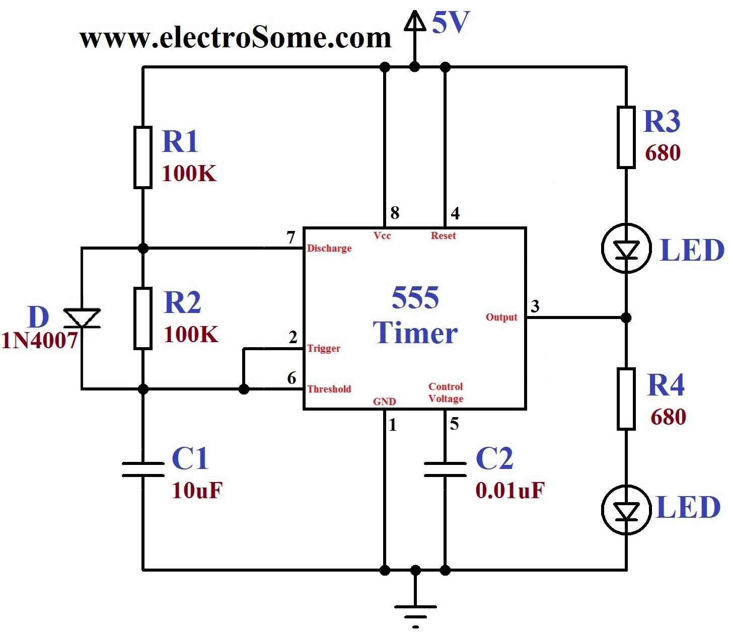
Fig-3:555 timer astable configurationThe figure-3 mentions 555 timer in astable configuration. As shown, astable circuit connects trigger pin to capacitor. It adds a resistor between the discharge and threshold pins. As mentioned astable circuit triggers from previous output pulse. Monostable circuit requires an externally applied trigger.
In short, the output pin oscillates from high to low creating a series of pulses as the capacitor charge oscillates from 33.3% to 66.6% Vcc, without any external triggers.
The duration the output pin stays high (tHIGH) is expressed as follows:
tHIGH=0.693*C1*(R1+R2)
The duration the output pin stays low (tLOW) is expressed as below:
tLOW=0.693*C1*R2
The frequency (f) of the series of pulses is expressed as follows:
f = 1/(tHIGH + tLOW)
Applications of 555 timer in astable configuration.
• modulation of ultrasonic and IR transmitters
• Turn ON and OFF an actuator at set time intervals for a fixed duration.
• create an accurate clock signal.
555 timer in monostable configuration
Touch Sensor Using 555 Timer Applications
Fig-4:555 timer monostable configurationThe figure-4 mentions 555 timer in monostable configuration. The Monostable circuit outputs one pulse for each high to low transition of the trigger pin. The output will return to the 'stable' state after a period of time that is a function of the attached resistor and capacitor values.
The length of the output pulse depends on when the capacitor reaches 66.6% Vcc. This rate is determined by the charge capacity of the capacitor (C1) and resistance (R1). The length of the output pulse(tp) is expressed as follows.
tp = 1.1 *R1*C1
Applications of 555 timer in monostable configuration.
• Debounce a momentary or push button switch
• Turning on an actuator for a set period of time
• Turn an output from a resistive sensor from analog signal to digital signal